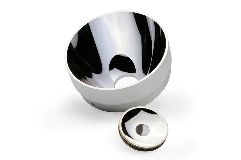
Although a mirror’s surface appears smooth to the naked eye, if you looked at it through a microscope you’d see many peaks and valleys. These surface imperfections can cause interference with light waves and other electromagnetic radiation. For this reason, understanding the degree and nature of this interference is crucial to successfully designing a metal based optical system.
All optics have varying degrees of surface roughness depending on how they’re manufactured, as well as the materials used. The roughness average (Ra) and root-mean-square (RMS) of a surface are two measurements that can help you characterize roughness. Using non-contact profilometry, Ra is calculated by taking the arithmetic mean average of the peaks and valleys on a surface. RMS is obtained by squaring the height values of each peak, calculating the mean average and then taking the square root of that value.
Although RMS is more mathematically accurate, neither measurement is a perfect parameter for calculating true optical performance. In short, these estimations are “close enough” for practical applications when compared to what the ideal surface should be.
An Easy Tool to Help
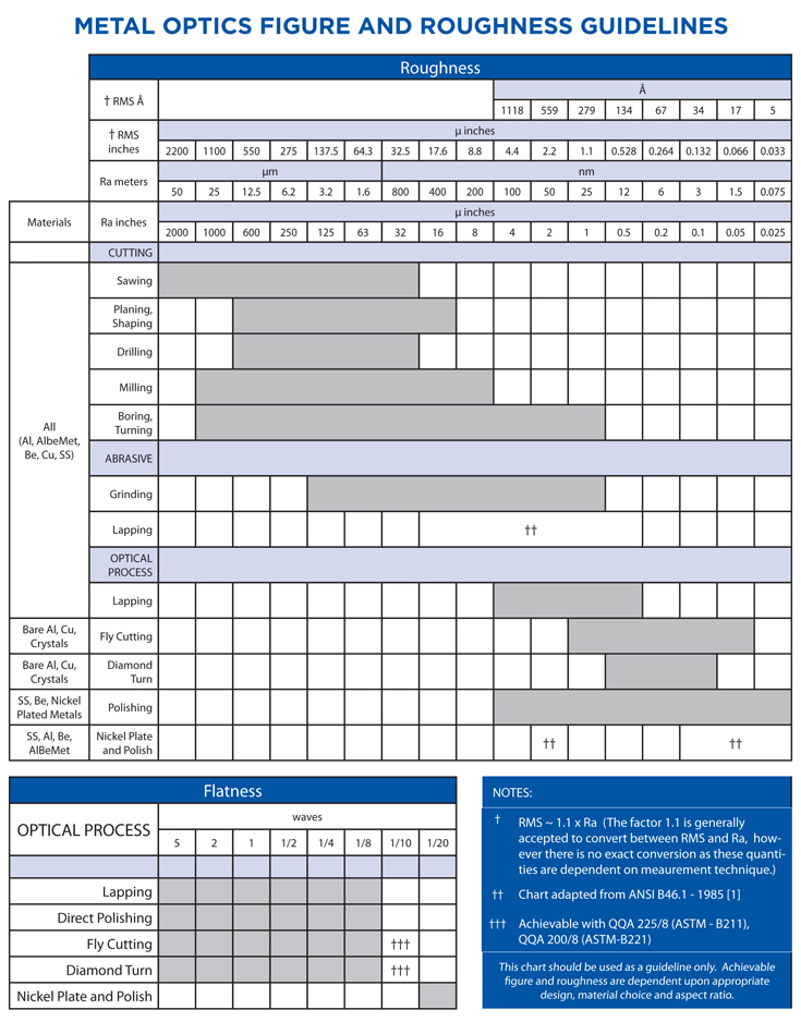
To simplify the process of designing a metal optic that best suits your application, our Guidelines for Metal Optics show the degree of roughness for various manufacturing methods and materials. These guidelines also show the optic flatness based on the manufacturing method. These guidelines are based on ANSI B46.1-1985 standards and represent the quality ranges possible with these methods.
Depending on your application needs, you may wish to combine methods, leading to more complex roughness calculations. Whatever your needs, our guidelines are a good starting point to see what methods and materials best suit your application.